15m CW transceiver MFJ-9315K
![]()
Japanese & English : Apr. 23, 2016
Last update : Apr. 23, 2016
Japanese page is here.
 Overview of MFJ-9315K
I built a 15m CW transceiver 'MFJ-9315K' in September 2015. Its manufacturer's
webpage is here. We can download the product and assembly manuals from this site. RF output of my MFJ-9315K is 1 watt.
In addition, I built a 80m CW transceiver 'MFJ-9380K' at the same time.
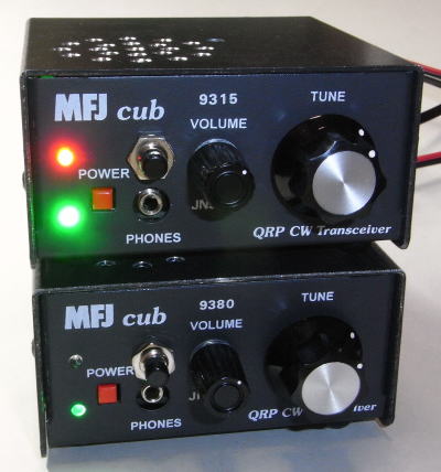
My MFJ-9315K (upper) and MFJ-9380K (lower)
( For modification, a push switch and an LED are added on the front panel.
)
( There are holes on the top plate for speaker addition. )
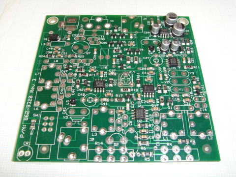
MFJ-9315K PC board before building
MFJ-9315K PC board
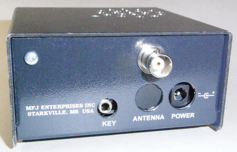
Rear panel of my MFJ-9315K
( A BNC connector is installed at the upper hole, instead of a RCA jack at the lower hole. )
( 'FREQ-mite' is fixed by the screw on the upper-left. )
My MFJ-9315K overview (modification points)
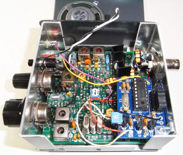
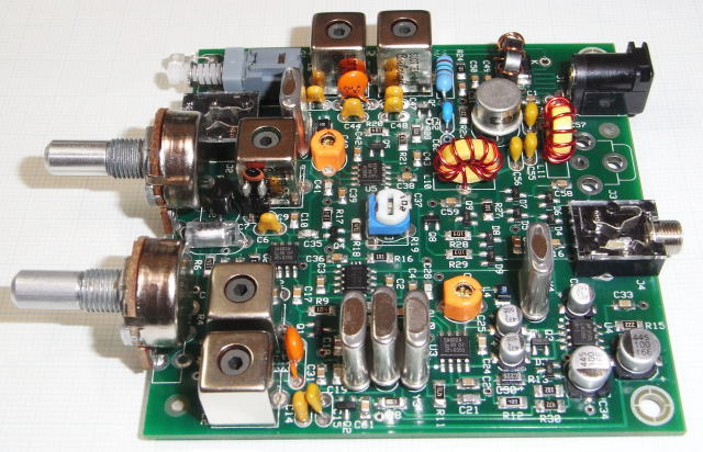
Inside of my MFJ-9315K
( There is a 'FREQ-mite' in the right front. )
( There is a speaker on the top plate. )
Main modification points are as follows:
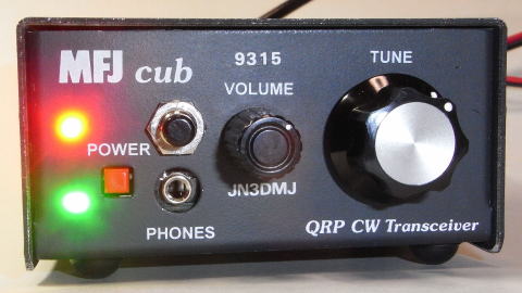
Front panel of my MFJ-9315K
( A push switch, an LED and some letters are added on the front panel.
)
Expansion of the frequency range
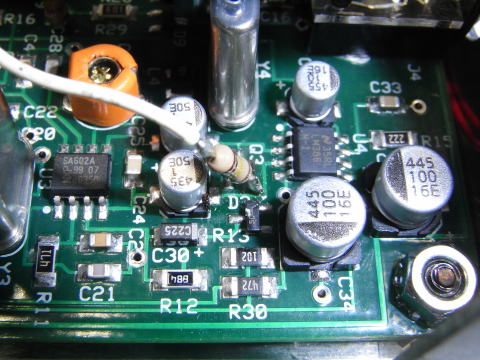
In order to make the frequency range wide, I changed C9 to be shown in the table.
| C9 | Frequency range |
Remarks |
| Original : 10pF | 21.000〜21.059MHz | |
| 15pF | 21.000〜21.092MHz | Current set value |
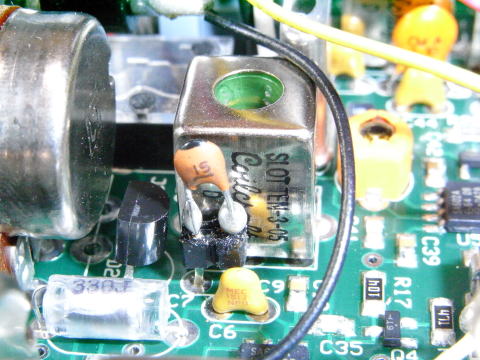
C9 which influences the frequency range - 15pF at the center of the image
As frequency range is more than 90kHz, tuning is slightly difficult for me. Therefore, I think that 70-75kHz is better.
Frequency indication
In order to indicate the frequency, Dave Benson K1SWL's 'FREQ-mite' supplied by the Four State QRP Group, a Morse-readout frequency-annunciating device, is installed, and a push switch is added on the front panel.
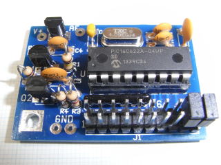
'FREQ-mite' ( left photo )
AF signal ( Morse code sound ) injection point is the additional 100k ohm
resistor in the center. ( right photo )
Upgrading of the low-pass filter after the final transistor
One more stage is added to the low-pass filter after the final transistor.
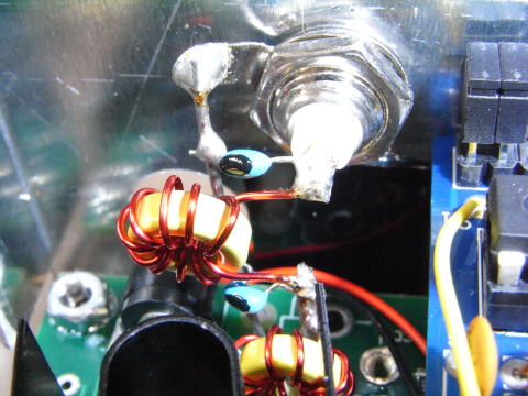
Added stage of the low-pass filter after the final transistor
Alternative final transistor
According to the assembly manual, the RF output could improve if the final
transistor 2N5109 is changed for 2N3553. Therefore I purchased some 2N3553s
from an American shop and tried to change it.
However, I gave up the changing, because the RF output became zero.
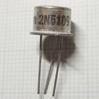
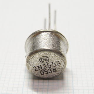
Original final transistor 2N5109 (left photo)
Alternative final transistor 2N3553 (right photo)
![]()
![]()
![]()
Copyright (C) 2016 by MATSUMOTO Koichi, JN3DMJ