40m CW transceiver SST40
![]()
Japanese : Jul. 13, 2009, English : Aug. 10, 2011
Last update : Sep. 10, 2016
Japanese page is here.
 Overview of the SST
I built a 40m CW transceiver SST40 in June 2006.
I added a speaker to my SST40 in Jan. 2013.
I continuously modify it.
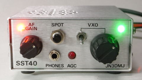
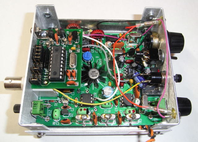
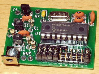
My SST40
( For modification, a push switch, a toggle switch, two LEDs are added
on the front panel. )
( There are holes on the top plate for speaker addition. )
SST ( The Simple Superhet Transceiver ) is a QRP CW transceiver kit, which
had been supplied by the Wilderness Radio.
SST had been distributed by the Electro Design Co. for Japanese users.
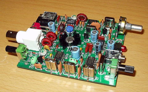
SST40 PC board
( Because trimmers and jacks are installed on the PC board, there is not
wiring and so it is easy to build. )
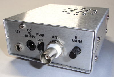
Rear panel of my SST
( 'FREQ-mite' is fixed by the screw on the upper-left. )
( From the left, key, power supply, power supply external / internal switch, antenna, RX RF gain. )
( There are holes on the top plate for speaker addition. )
My SST40 overview (modification points)
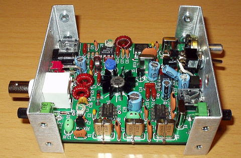
Inside of my SST40 before 'FREQ-mite' is installed
( There are no wiring. )
Inside of my SST40 after 'FREQ-mite' is installed
Major modification points of my SST40 are as follows.
Expansion of the frequency range
Two kinds of variable capacitance diodes are included in the SST kit to
select the frequency range when a user build.
In order to make the frequency range wide, I modified my SST to be able
to change the two kinds of variable capacitance diodes with the toggle
switch added on the front panel.
Two kinds of variable capacitance diodes with a toggle switch
A ceramic capacitor from 2 to 4pF is added in parallel to the crystal in the VXO ( variable frequency crystal oscillator ).
| Month, Year | Capacitor added in parallel to the crystal in the VXO | Frequency range ( Lower ) |
Frequency range ( Upper ) |
Remarks |
| June 2006 | None | 7.01017~7.01968MHz | 7.01799~7.02544MHz | |
| 2.5 pF ( two 5pF capacitors in series ) | 7.00128~7.01782MHz | 7.01567~7.02520MHz | Set value in 2006 | |
| 3pF | 6.99882~7.01762MHz | 7.01529~7.02521MHz | ||
| Jan. 2013 | 2.72pF ( 5pF and 6pF capacitors in series ) | 7.00671~7.01939MHz | 7.01882~7.02607MHz | |
| 3pF | 7.00548~7.01908MHz | 7.01848~7.02594MHz | ||
| 4pF | 6.99932~7.01822MHz | 7.01766~7.02592MHz | Current set value |
Pitch frequency and BFO frequency adjustment
The pitch frequency (CW offset) can be adjusted by changing C24.
In order to make the pitch frequency close to 700Hz, C24 was changed from
56pF fixed capacitor to 50pF trimcap and fixed 33pF in parallel.
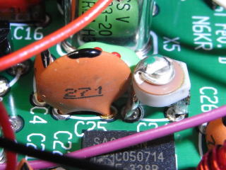
C24 changed to 50pF trimcap and fixed 33pF (Left photo)
C10 changed to 50pF trimcap (Right photo)
| Month, Year | C24 | Pitch frequency | Remarks |
| June 2006 | 33pF | 590Hz | |
| 47pF | 744Hz | Set value in 2006 | |
| 68pF | 890Hz | ||
| Jan. 2013 | 43pF | 720Hz | Set value in 2013 |
| Oct. 2015 | 50pF Trimcap and fixed 33pF in parallel |
570-870Hz (Set to 700Hz) |
Current (BFO frequency changed too) |
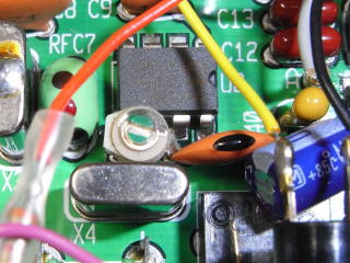
The BFO frequency can be adjusted by changing C10.
In order to set the center frequency of CW filter passband after product
detector close to 700Hz, C10 was changed from 22pF fixed capacitor to 50pF
trimcap.
Frequency indication
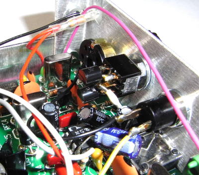
In order to indicate the frequency, Small Wonder Labs 'FREQ-mite' ( As of May 2015, we can get it from Four State QRP Group. ), a Morse-readout frequency-annunciating device, is installed, and a push switch is added on the front panel.
Small Wonder Labs 'FREQ-mite'
AF signal ( Morse code sound ) injection point is the additional 100k ohm
resistor in the center.
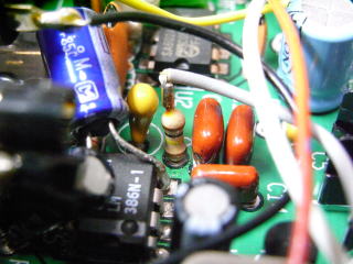
Upgrading of the filters
For spurious reduction, the band-pass filter after the transmit mixer was upgraded to two stages from one stage.
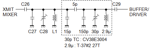
Circuit diagram of the upgraded band-pass filter
( The part surrounded in a dotted line is added. )
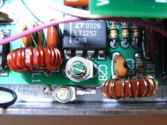
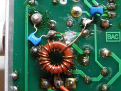
Upgraded band-pass filter
Side view ( Left photo : Right coil was added. )
Top view ( Center photo : Yellow trimming capacitor was added. )
Bottom view ( Right photo : Three capacitors were added. )
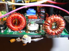
For harmonics reduction, the low-pass filter after the final transistor was upgraded to three stages from two stages.
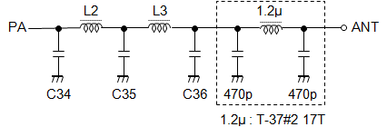
Circuit diagram of the upgraded low-pass filter
( The part surrounded in a dotted line was added. )
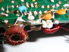
Added part of the upgraded low-pass filter
( I cut the circuit pattern of the solder side, and installed a coil and
two capacitors. )
The above-mentioned filters upgrading is very effective.
SST Links
A picture of my SST was published in a great blog of Dave AA7EE in USA.
His SST is a complete own work product based on the original N6KR SST.
Please visit his blog. In addition to circuital invention, his building
technology is excellent and his SST is beautiful artistically.
![]() Dave Richards AA7EE' s blog -- A Scratch-Build of N6KR and Wilderness Radio’s SST for 20M
Dave Richards AA7EE' s blog -- A Scratch-Build of N6KR and Wilderness Radio’s SST for 20M
MePADs and MeSQUAREs of QRPme used in his SST are interesting.
Past images from June 2006 to Oct. 2015 are here(Japanese).
![]()
![]()
![]()
Copyright (C) 2011-2016 by MATSUMOTO Koichi, JN3DMJ