80m CW transceiver MFJ-9380K
![]()
Japanese & English : Apr. 23, 2016
Last update : Apr. 23, 2016
Japanese page is here.
 Overview of MFJ-9380K
I built a 80m CW transceiver 'MFJ-9380K' in September 2015. Its manufacturer's
webpage is here. We can download the product and assembly manuals from this site. RF output
of my MFJ-9380K is 2.4 watts.
In addition, I built a 15m CW transceiver 'MFJ-9315K' at the same time.
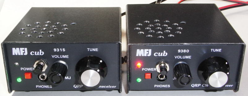
My MFJ-9315K (left) and MFJ-9380K (right)
( For modification, a push switch and an LED are added on the front panel.
)
( There are holes on the top plate for speaker addition. )
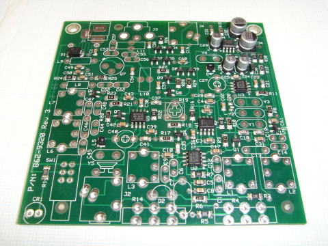
MFJ-93xxK PC board before building
MFJ-9380K PC board
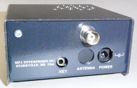
Rear panel of my MFJ-9380K
( A BNC connector is installed at the upper hole, instead of a RCA jack at the lower hole. )
( 'FREQ-mite' is fixed by the screw on the upper-left. )
My MFJ-9380K overview (modification points)
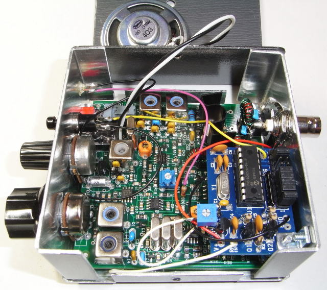
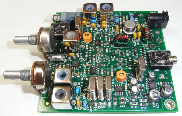
Inside of my MFJ-9380K
( There is a 'FREQ-mite' in the right front. )
( There is a speaker on the top plate. )
Main modification points are as follows:
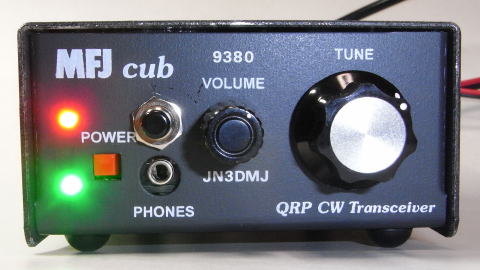
Front panel of my MFJ-9380K
( A push switch, an LED and some letters are added on the front panel.
)
Reverse rotatory direction of the tune control
Because MFJ-9380K and MFJ-9340K use subtractive mixing, operating frequency
decreases as rotating the tune control R4 clockwise.
Therefore I changed the connection of the PC board to increase the operating
frequency as rotating the tune control R4 clockwise.
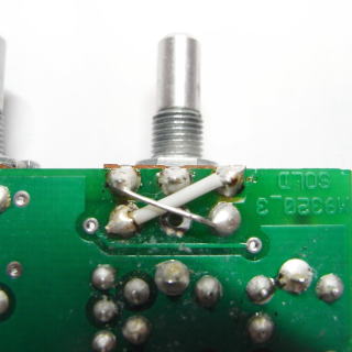
Changing the connection of the PC board of the part of tune control R4
to increase the operating frequency as rotating the tune control R4 clockwise.
Cut four places in total - front and back - of the circuit board patterns (left and right photos).
Reverse right and left and connect them (right photo).
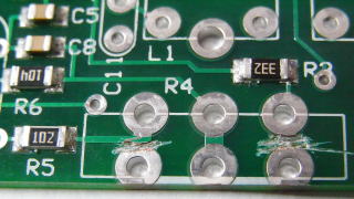
Expansion or reduction of the frequency range
Frequency range can be extended or reduced by changing C9.
As a result of examination, I decided to leave C9 the original value.
| C9 | Frequency range |
Remarks |
| Original : 27pF | 3.500〜3.565MHz | Current set value |
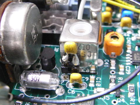
C9 which influences the frequency range - 27pF at the center of the image
Frequency indication
In order to indicate the frequency, Dave Benson K1SWL's 'FREQ-mite' supplied by the Four State QRP Group, a Morse-readout frequency-annunciating device, is installed, and a push switch is added on the front panel.
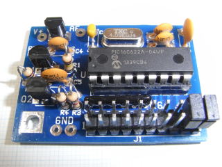
'FREQ-mite' ( left photo )
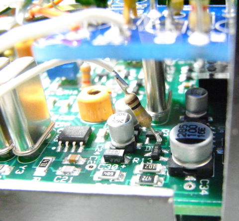
AF signal ( Morse code sound ) injection point is the additional 100k ohm
resistor in the center. ( right photo )
Upgrading of the low-pass filter after the final transistor
One more stage is added to the low-pass filter after the final transistor.
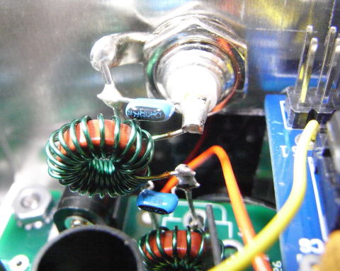
Added stage of the low-pass filter after the final transistor
Alternative final transistor
According to the assembly manual, the RF output could improve if the final
transistor 2N5109 is changed for 2N3553. Therefore I purchased some 2N3553s
from an American shop and tried to change it.
However, I gave up the changing, because the RF output decreased from 2.4
watts to 0.9 watt.
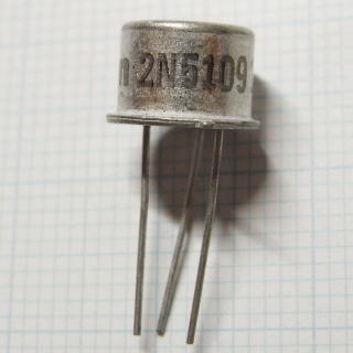
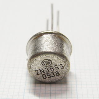
Original final transistor 2N5109 (left photo)
Alternative final transistor 2N3553 (right photo)
![]()
![]()
![]()
Copyright (C) 2016 by MATSUMOTO Koichi, JN3DMJ