Remote control of amateur radio station using internet. (My remote shack) KENWOOD TS-590S and TS-590SG, ICOM IC-PW1, YAESU FL-7000, 7 antennas.(6 coaxial cables) and Can turn the mast. Ver.1.2 02 Sep. 2022 Ver.1.1 26 Jan. 2018 Ver.1.0 07 Nov. 2015 All rights reserved JA3OOK Toshikazu Nakamura Ver.1.1 26 Jan. 2018 I replased KENWOOD TS-590S to TS-590SG. In the following sentences, a reading, please exchange TS-590S with TS-590SG. Ver.1.0 07 Nov. 2015 This is technical explanation of my remote shack. I got much advices and hints from a member of our club station and many friend, when I designed and made this. I thank you. When I explain it, I use the next words as needed. "transmitting Station" : The place with the radio facilities such as transceivers and antennas. The Internet comes, and here is the PC and a router. "Remote control place" : The place that stays away from the transmitting station, and remote control the radio facilities of the transmitting station. The Internet comes, and here is the PC and a router, too.
 Firstly I write my remote contoled rigs and antennas etc.
Secondly, I write what is possible by remote control. and it methods.
Last, I write the some main components.
1. My remote contoled rigs and antennas etc
transmitting Station
* KENWOOD TS-590S
* ICOM IC-PW1 and YAESU FL-7000
* Antenna 160m to 10m band. and use 6 coaxial cables.
* Windows PC
There is the following thing in the Remote control place
* Windows PC
* Microphone, Electronic Keyer
2. What is possible by remote control
a. Automatically selecting band of antenna cables and liner amplifiers
I made the "ABS" that is my handmade boaud.
ABS receive RS-232C data from TS-590. And has following functions.
* ABS analyzes TS-590 PC command from RS-232C.
* It select the antenna relay corresponding to the band.
* It generate CI-V signal for PW-1 and BAND DATA for FL-7000.
The detailed thing, Please look at Clause 3.1
b. Remote control of AC Power ON/OFF etc. of liner amplifiers
* AC power ON/OFF
* Amplifier/Standby
The detailed thing, Please look at Clause 3.2 about PW1, Clause 3.3 about FL-7000.
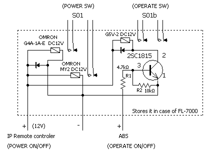
c. ON/OFF of the PC power of transmitting Station
With an original internet IP address, The equipment which can ON/OFF some lines is
sold.
I decide to call this "IP remote controler".
I obtained "PIC-NIC" which was a kind of "IP remote controler".
The detailed thing about "PIC-NIC", Please look at Clause 3.5.
I drag the line to power SW which open the inside of the PC, and conect to PIC-NIC.
Of course I tie PIC-NIC to the router of the transmitting station by LAN.
By this method, I can startup and shutdown of the Windows-OS with ON/OFF of the
PC power from the distant place.
d. Rotate antenna tower mast
Use two control line of "IP remote controler".
One is for PC power ON/OFF and rotation to left.
When power of the tranceiver is OFF, use ON/OFF of PC power.
When power of the tranceiver is ON, use rotation to left.
What I use in common is for the prevention of the operation mistake. I do not
want to cut a PC power supply suddenly.
Other one is for rotation to right.
A swichi board is produced using some relays to realize the above.
View of direction of beam antenna is by using animation image of the Skype.
e. Sending by CW not fixed sentence
I made "the CW-VOX board" that convert CW monitor audio signal to Key-down.
f. Operation of KENWOOD TS-590
Use ARHP-590 and ARCP-590 by KENWOOD.
The transmission and reception sound uses Skype, too.
g. ON/OFF of main AC100V/200V
When the PC is switched ON, 5V comes out to a USB terminal. The 5V join to relay,
and the relay performs ON/OFF of AC main power.
3. Some main components.
3.1 ABS (At 2nd Sep. 2022 Newly designed ABS was maked,
so revised circuits, photos and descriptions related to ABS.)
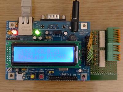
ABS:Automatic Band Selection board.
It was designed with micro computer "PIC" and was programed C-language by me.
The board analyzes TS-590 PC command.
And it select the antenna relay and band SW of liner amplifier, corresponding
to the band.
In case of FL-7000, ON/OFF of OPERATE SW.
TS-590S----RS232C----ABS(PIC)----Relay(select cables)
/ |
/ |
CI-V / |BAND DATA
/ |
/ |
PW1 FL-7000
Since ON/OFF of OPERATE SW can be done by IP remote controller, it is deleted from newly designed ABS.
Hardware circuit
USART in micro chip is necessary two sets, for TS-590(RS-232C) and PW1(CI-V).
I chose micro computer is PIC18F25k.
I adopted photocoupler(TLP627) for the driver of the antenna swiching relay.
Firstly I write my remote contoled rigs and antennas etc.
Secondly, I write what is possible by remote control. and it methods.
Last, I write the some main components.
1. My remote contoled rigs and antennas etc
transmitting Station
* KENWOOD TS-590S
* ICOM IC-PW1 and YAESU FL-7000
* Antenna 160m to 10m band. and use 6 coaxial cables.
* Windows PC
There is the following thing in the Remote control place
* Windows PC
* Microphone, Electronic Keyer
2. What is possible by remote control
a. Automatically selecting band of antenna cables and liner amplifiers
I made the "ABS" that is my handmade boaud.
ABS receive RS-232C data from TS-590. And has following functions.
* ABS analyzes TS-590 PC command from RS-232C.
* It select the antenna relay corresponding to the band.
* It generate CI-V signal for PW-1 and BAND DATA for FL-7000.
The detailed thing, Please look at Clause 3.1
b. Remote control of AC Power ON/OFF etc. of liner amplifiers
* AC power ON/OFF
* Amplifier/Standby
The detailed thing, Please look at Clause 3.2 about PW1, Clause 3.3 about FL-7000.
c. ON/OFF of the PC power of transmitting Station
With an original internet IP address, The equipment which can ON/OFF some lines is
sold.
I decide to call this "IP remote controler".
I obtained "PIC-NIC" which was a kind of "IP remote controler".
The detailed thing about "PIC-NIC", Please look at Clause 3.5.
I drag the line to power SW which open the inside of the PC, and conect to PIC-NIC.
Of course I tie PIC-NIC to the router of the transmitting station by LAN.
By this method, I can startup and shutdown of the Windows-OS with ON/OFF of the
PC power from the distant place.
d. Rotate antenna tower mast
Use two control line of "IP remote controler".
One is for PC power ON/OFF and rotation to left.
When power of the tranceiver is OFF, use ON/OFF of PC power.
When power of the tranceiver is ON, use rotation to left.
What I use in common is for the prevention of the operation mistake. I do not
want to cut a PC power supply suddenly.
Other one is for rotation to right.
A swichi board is produced using some relays to realize the above.
View of direction of beam antenna is by using animation image of the Skype.
e. Sending by CW not fixed sentence
I made "the CW-VOX board" that convert CW monitor audio signal to Key-down.
f. Operation of KENWOOD TS-590
Use ARHP-590 and ARCP-590 by KENWOOD.
The transmission and reception sound uses Skype, too.
g. ON/OFF of main AC100V/200V
When the PC is switched ON, 5V comes out to a USB terminal. The 5V join to relay,
and the relay performs ON/OFF of AC main power.
3. Some main components.
3.1 ABS (At 2nd Sep. 2022 Newly designed ABS was maked,
so revised circuits, photos and descriptions related to ABS.)
ABS:Automatic Band Selection board.
It was designed with micro computer "PIC" and was programed C-language by me.
The board analyzes TS-590 PC command.
And it select the antenna relay and band SW of liner amplifier, corresponding
to the band.
In case of FL-7000, ON/OFF of OPERATE SW.
TS-590S----RS232C----ABS(PIC)----Relay(select cables)
/ |
/ |
CI-V / |BAND DATA
/ |
/ |
PW1 FL-7000
Since ON/OFF of OPERATE SW can be done by IP remote controller, it is deleted from newly designed ABS.
Hardware circuit
USART in micro chip is necessary two sets, for TS-590(RS-232C) and PW1(CI-V).
I chose micro computer is PIC18F25k.
I adopted photocoupler(TLP627) for the driver of the antenna swiching relay.
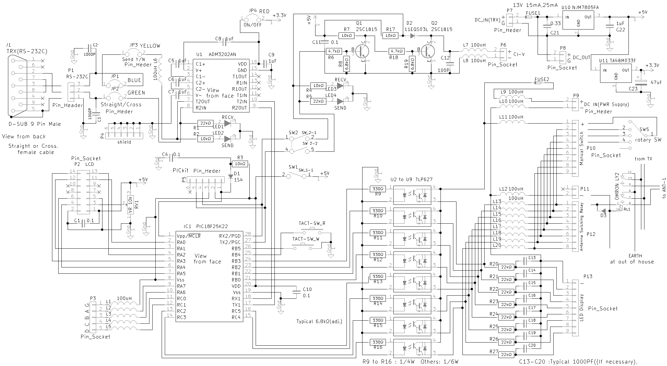
 Following circuit is from the photocoupler(TLP627) in ABS to antenna swiching relay.
And LED for indicate to using band. There is also a manual switch in case it breaks or
for testing.
Following circuit is from the photocoupler(TLP627) in ABS to antenna swiching relay.
And LED for indicate to using band. There is also a manual switch in case it breaks or
for testing.
 Program on micro computer:PIC18F25K22. I wrote the program by C.
The PIC receive PC command from TS-590 via USART1.
PC command is written in Reference materials 1 "PC CONTROL COMMAND REFERENCE
FOR THE TS-590S TRANSCEIVER".
The PIC analize "IF command".
And assemble frequency data by CI-V format,
and make the transmission to PW1 via USART2.
The constitution of CI-V data is written in Reference materials 2 "CT-17
INSTRUCTION MANUAL".
As same as, It is ON/OFF in applicable port RC2-RC5,RB0-RB3 corresponding to BAND
for the photocoupler of the antenna swiching relay, .
As same as, It is ON/OFF in applicable port RC0 - RC03 corresponding to YAESU BAND DATA.
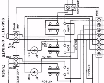
3.2 Remote Control IC-PW1
The switch which operation is necessary for by remote use of PW1 is three
of the next.
(as for the initial setting and the driving preparations finishedThat precocious)
* POWER SW
* AMP/PROTECT SW
* BAND SW------The automatic change of BAND SW is realized in ABS(described section 3.1).
(It is linked by a band change of TS-590)
3.2.1 Remote control to POWER SW and AMP/PROTECT SW
3.2.1.1 Realized method 1 (the use of the solenoid)
I think that the structure can understand it immediately if you look
the next photograph.
Program on micro computer:PIC18F25K22. I wrote the program by C.
The PIC receive PC command from TS-590 via USART1.
PC command is written in Reference materials 1 "PC CONTROL COMMAND REFERENCE
FOR THE TS-590S TRANSCEIVER".
The PIC analize "IF command".
And assemble frequency data by CI-V format,
and make the transmission to PW1 via USART2.
The constitution of CI-V data is written in Reference materials 2 "CT-17
INSTRUCTION MANUAL".
As same as, It is ON/OFF in applicable port RC2-RC5,RB0-RB3 corresponding to BAND
for the photocoupler of the antenna swiching relay, .
As same as, It is ON/OFF in applicable port RC0 - RC03 corresponding to YAESU BAND DATA.
3.2 Remote Control IC-PW1
The switch which operation is necessary for by remote use of PW1 is three
of the next.
(as for the initial setting and the driving preparations finishedThat precocious)
* POWER SW
* AMP/PROTECT SW
* BAND SW------The automatic change of BAND SW is realized in ABS(described section 3.1).
(It is linked by a band change of TS-590)
3.2.1 Remote control to POWER SW and AMP/PROTECT SW
3.2.1.1 Realized method 1 (the use of the solenoid)
I think that the structure can understand it immediately if you look
the next photograph.
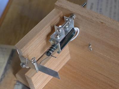
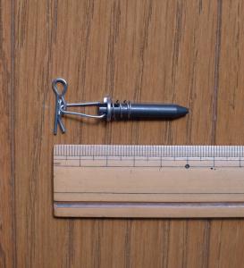 The solenoid make a lot of vibration and noise. I recommend Realized method 2 (the use of Servomotor).
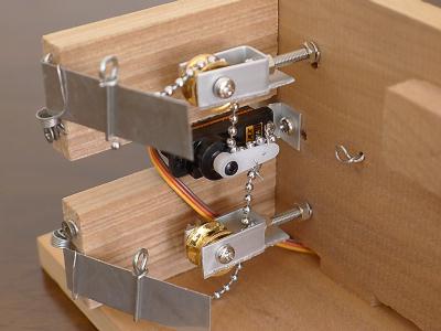
3.2.1.2 Realized method 2 (the use of Servomotor)
The structure is the next photograph.
The solenoid make a lot of vibration and noise. I recommend Realized method 2 (the use of Servomotor).
3.2.1.2 Realized method 2 (the use of Servomotor)
The structure is the next photograph.
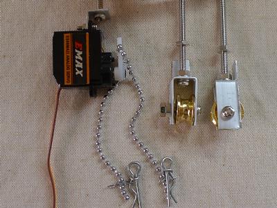
 3.2.2 The board of Control Solenoid and Serrvomotor
I made the board with PIC(micro computer).
3.2.2.1 for Solenoid
3.2.2 The board of Control Solenoid and Serrvomotor
I made the board with PIC(micro computer).
3.2.2.1 for Solenoid
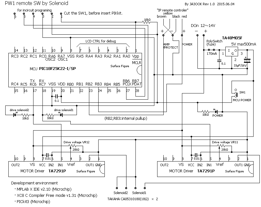
 I use the driver IC "TA7291P" by TOSHIBA.
3.2.2.2 for Servomotor
I use the driver IC "TA7291P" by TOSHIBA.
3.2.2.2 for Servomotor
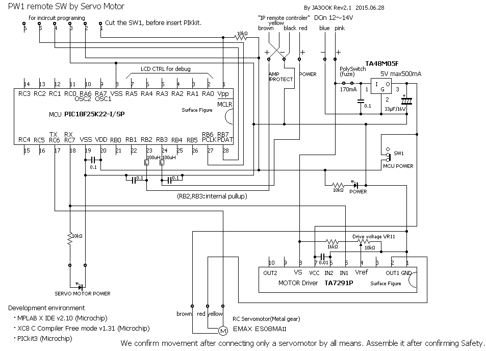
 The number of motors is one. So the driver IC gets off with one, too.
Caution
Power is strong with the servomotor such as the toy.
If you produce it. You are hurt and break the power switch by false wiring and
a programming error and other carelessness.
Please perform the test carefully.
3.2.3 How to use this board
The board for solenoid or servomotor be connected to "IP remote controler".
And, remote control to "IP remote controler" from Remote control place.
3.3 Remote control FL-7000
The switch which operation is necessary for by remote use of FL-7000 is three of the next.
( (After the initial setting and the driving preparations finished)
* POWER SW
* OPERATE SW
* BAND SW------The automatic change of BAND SW is realized in ABS(described section 3.1).
(It is linked by a band change of TS-590)
There are two types about FL-7000, with SW for SSB/RTTY and with no SW.
My FL-7000 does not have it.
(let's make drive power half at the time of the RTTY use)
3.3.1 How to remote control of POWER SW
I change the wiring from S01 of FL-7000 to Two relays.
One the relay use for AC200V ON/OFF. It has to be able to tolerate AC200V/20A.
1 circuit 1 points of contact.
Other One the relay use for weak. Small relay is Ok.
1 circuit 1 points of contact.
I operate the relay with "IP remote control".
The number of motors is one. So the driver IC gets off with one, too.
Caution
Power is strong with the servomotor such as the toy.
If you produce it. You are hurt and break the power switch by false wiring and
a programming error and other carelessness.
Please perform the test carefully.
3.2.3 How to use this board
The board for solenoid or servomotor be connected to "IP remote controler".
And, remote control to "IP remote controler" from Remote control place.
3.3 Remote control FL-7000
The switch which operation is necessary for by remote use of FL-7000 is three of the next.
( (After the initial setting and the driving preparations finished)
* POWER SW
* OPERATE SW
* BAND SW------The automatic change of BAND SW is realized in ABS(described section 3.1).
(It is linked by a band change of TS-590)
There are two types about FL-7000, with SW for SSB/RTTY and with no SW.
My FL-7000 does not have it.
(let's make drive power half at the time of the RTTY use)
3.3.1 How to remote control of POWER SW
I change the wiring from S01 of FL-7000 to Two relays.
One the relay use for AC200V ON/OFF. It has to be able to tolerate AC200V/20A.
1 circuit 1 points of contact.
Other One the relay use for weak. Small relay is Ok.
1 circuit 1 points of contact.
I operate the relay with "IP remote control".
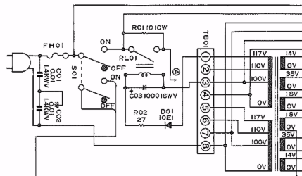 3.3.2 How to remote control of OPERATE SW
I change the wiring from S01b of FL-7000 to the small relay.
2 circuit 1 points of contact.
I operate the relay with "IP remote control".
3.3.2 How to remote control of OPERATE SW
I change the wiring from S01b of FL-7000 to the small relay.
2 circuit 1 points of contact.
I operate the relay with "IP remote control".
 3.3.3 Relay Driver's circuit
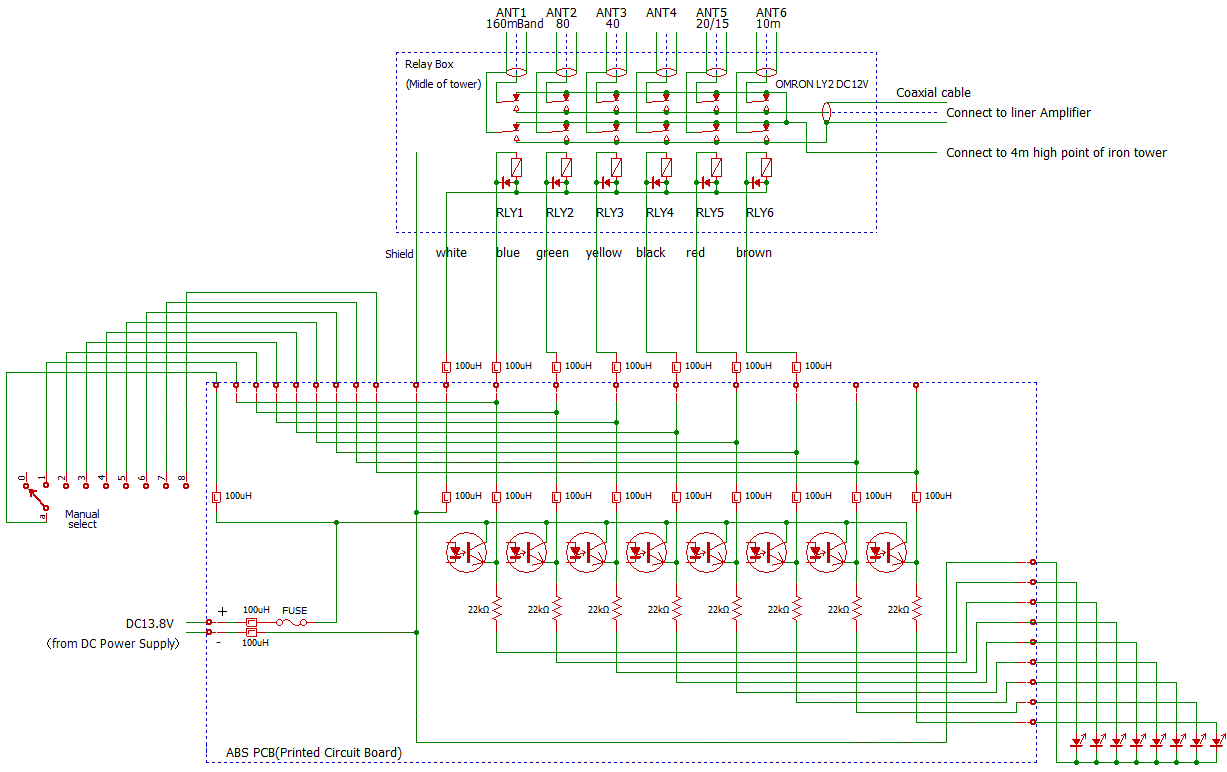
 3.3.4 How to remote change of band
Micro computer in ABS(described section 3.1) is ON/OFF in applicable port RC0 - RC03.
The ports is corresponding to YAESU BAND DATA.
Connect the ports to ACC-2 terminal of FL-7000.
The correspondence of the pin number of the ACC-2 terminal of FL-7000 and BAND DATA is as follows.
DATA GND D C B A Hex
Pin# Pin1 Pin2 Pin3 Pin4 Pin5
160m 0 0 0 1 01x
80m 0 0 1 0 02x
40m 0 0 1 1 03x
30m 0 1 0 0 04x
20m 0 1 0 1 05x
17m 0 1 1 0 06x
15m 0 1 1 1 07x
12m 1 0 0 0 08x
10m 1 0 0 1 09x
6m 1 0 1 0 0Ax
The above-list depends on reference materials 3. I thanks for author M1MBX.
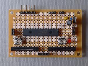
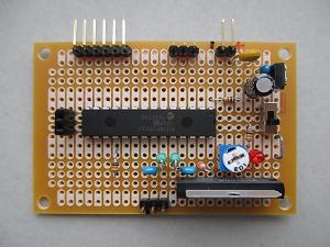
3.4 Photograph of hand made board
These are boards becoming the basis of the remote control.
3.3.4 How to remote change of band
Micro computer in ABS(described section 3.1) is ON/OFF in applicable port RC0 - RC03.
The ports is corresponding to YAESU BAND DATA.
Connect the ports to ACC-2 terminal of FL-7000.
The correspondence of the pin number of the ACC-2 terminal of FL-7000 and BAND DATA is as follows.
DATA GND D C B A Hex
Pin# Pin1 Pin2 Pin3 Pin4 Pin5
160m 0 0 0 1 01x
80m 0 0 1 0 02x
40m 0 0 1 1 03x
30m 0 1 0 0 04x
20m 0 1 0 1 05x
17m 0 1 1 0 06x
15m 0 1 1 1 07x
12m 1 0 0 0 08x
10m 1 0 0 1 09x
6m 1 0 1 0 0Ax
The above-list depends on reference materials 3. I thanks for author M1MBX.
3.4 Photograph of hand made board
These are boards becoming the basis of the remote control.
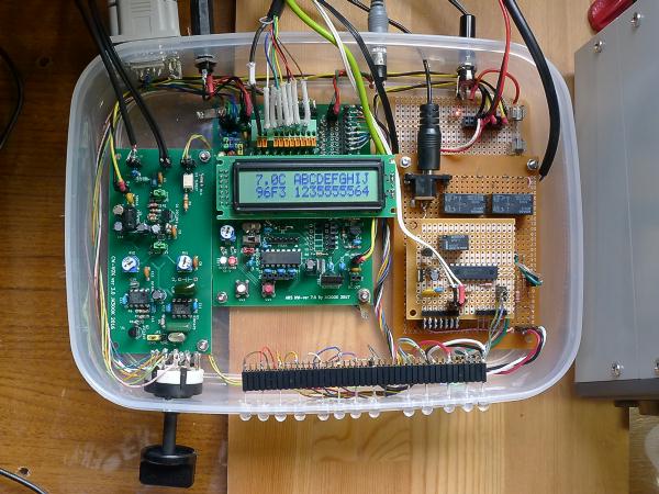 Left board :
CW-VOX board. Generate CW key-down signal by CW-monitor-tone.
It's desiged by me, use KiCad EDA( A Cross Platform and Open Source
Electronics Design Automation Suite).
Central board :
ABS(Automatic Band Selection board) with character LCD dispay.
Right board :
Swichi board of antenna rotate by internet.
3.5 PIC-NIC (IP Remote controler)
This is a board becoming the basis of the remote control, too.
With an original internet IP address, The equipment can ON/OFF some lines.
PIC-NIC is made by TriState. (Reference materials 5)
But, It is sold only in AKIZUKI-DENSHI.
Left board :
CW-VOX board. Generate CW key-down signal by CW-monitor-tone.
It's desiged by me, use KiCad EDA( A Cross Platform and Open Source
Electronics Design Automation Suite).
Central board :
ABS(Automatic Band Selection board) with character LCD dispay.
Right board :
Swichi board of antenna rotate by internet.
3.5 PIC-NIC (IP Remote controler)
This is a board becoming the basis of the remote control, too.
With an original internet IP address, The equipment can ON/OFF some lines.
PIC-NIC is made by TriState. (Reference materials 5)
But, It is sold only in AKIZUKI-DENSHI.
 I added small board right side. It is the Driver photocouplers and connecters.
In addition, I drew the connection diagram by "BSch3V:the curcuit diagram editor made by SUIGYO-DO". I thank you. Reference materials 1 KENWOOD "PC CONTROL COMMAND REFERENCE FOR THE TS-590S TRANSCEIVER" 2 ICOM "CT-17 INSTRUCTION MANUAL" 3 M1BXF "Icom (CI-V or band Data) to Yaesu BCD Band Data Converter" 4 YAESU MUSEN "FL-7000 INSTRUCTION MANUAL" 5 TriState PIC-NIC support page
Top
Goto JA3OOK Japanese Website Top