| automatic antenna tuner SRA-2300 | |
| I received the SRA-2300 one day from one of my business customers. The following is about the modifications I have made to the SRA-2300. Many thanks to G6LVI Mr.Patrick Hickey for help in creating this page. |
|
1.About the SRA-2300 |
|
| The Ranger Communications SRA-2300 is an automatic antenna tuner. The frequency range is 1.8 to 30MHz with a maximum RF input of 150watts (PEP). Fig.1 shows the component side lay-out of the SRA-2300. Fig.2 shows the connections to the SRA-2300. Connect an antenna (long wire with ground, or loop) and power the ATU with 13.8V. Apply an HF signal (AM or FM) of between 5 and 10W to the RF input terminal. The SRA-2300 should now start automatically tuning (you will hear the relays clatter as the ATU searches for a suitable impedance.) The RMTIND terminal will fall to a LOW level (0v), when tuning is completed successfully. |
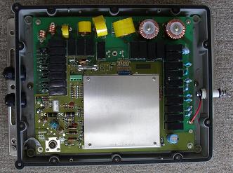 Fig.1 |
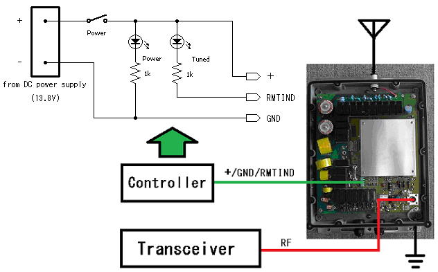 Fig.2 |
|
2.Reset function |
|
As Radio Amateurs, we often move operating frequency several hundred KHz in any given band. For example, you have been operating on 14.003MHz and the SWR is 1.2. You then need to move up to 14.300MHz and find that the SWR is unacceptable at 1.8. The SRA-2300 retuning threshold may be an SWR of 2.0 and will not retune. So, you need to persuade the SRA-2300 to initiate another tuning cycle somehow. To achieve this a RESET function is required. Fig.3 is a flowchart of the control software of the SRA-2300. (This is my interpretation) Interestingly, the circuit is provided for this function, but the necessary components have been omitted. The silk screened legend for the missing components are clearly marked on the PCB. A 3 pole power connector is fitted at position TB1 and the silk is marked RMTIND, +, GND and RESET. To include the RESET function a 4 pole connector is required. With the missing components fitted and the RESET terminal taken to ground (0v), the control CPU (MC6805) will reset. |
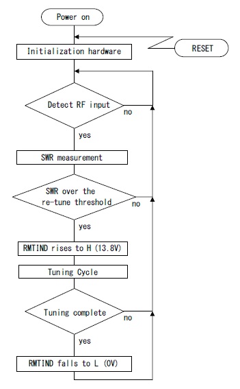 Fig.3 |
Fig.4 Shows the original circuit, components missing. |
|
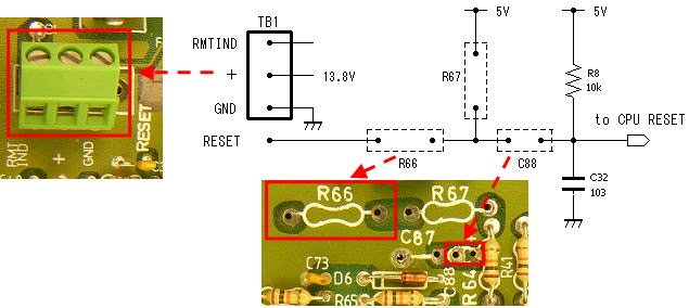 Fig.4 |
|
Fig.5 Shows the circuit with the missing components fitted to enable the RESET function. Change the 3 pole terminal to a 4 pole, add short wire links at R66 and C88. |
|
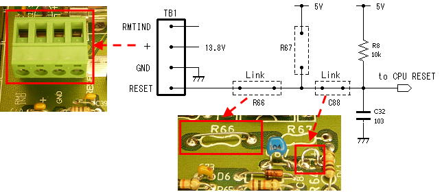 Fig.5 |
|
Fig.6 Shows the control circuit for using RESET function. |
|
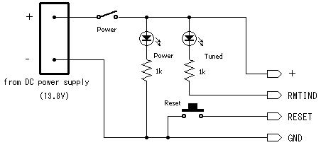 Fig.6 |
|
*** Why is the reset circuit in the SRA-2300 is omitted ? *** |
|
In this instance, the SRA-2300 was marketed with the commercial or PMR user in mind. It was also intended to be marketed by OEMs who would put their own badge on it and call it the SG-Something for example. Unlike Radio Amateurs, PMR or commercial radio users tend to use only the one frequency allocated by the licensing authority in any given band. The ATU is not required to retune once this frequency is stored in its memory. It will only do so when the next allocated frequency band is selected. (80M to 40M, 40M to 20M and so on.) It will re-tune whenever the band is changed. Under these circumstances I think the reset function is not necessary. |
|
3.LOCK function |
|
The frequency is changed within a band and the SWR is considered to be just about acceptable. This may be close to the automatic retune threshold. Under these circumstances there is a danger that the ATU may initiate a tuning cycle when the transmitter is operating at full power, which would cause severe damage to the relay contacts. (When tuning, RF power to the SRA-2300 should not be more than 10W.) A means of inhibiting the tuning cycle under these conditions would be useful, hence a LOCK function is required. Unfortunately this is not provided for on the PCB, so it needs the addition of a small circuit and one PCB track cut to make this possible. Fig.7 Shows the modification to provide both a RESET and a LOCK function. Change R66 to a diode*, add the link at C88 and make up the small additional circuit for the LOCK function on a small piece of Vero or similar board. On the solder side of the PCB cut the short piece of track linking pins 10 and 11 of 74HC10. * The diode at R66 should be of the Shottky type - having a lower forward voltage drop. The reason for this is to get the RESET voltage as near to 0V as possible. A 1N5817RL or equivalent seems to works well. This has a spec' Vf of 0.45V, although when used in this circuit the Vf is found to be considerably less, 0.148V typically. (1N4148 tests at around 0.598V) |
|
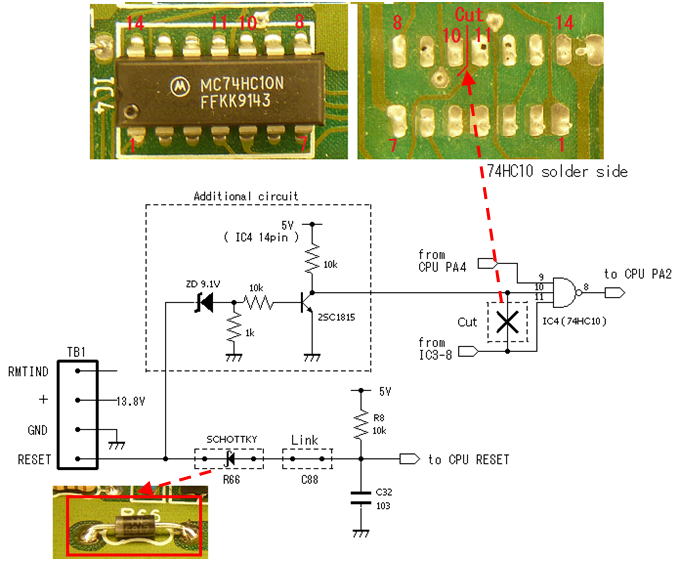 Fig.7 |
|
Fig.8 Shows is the control circuit for the RESET and LOCK function, and the actual control head. This controller can be used with the SG-230. (This is equivalent to the SGC SMART LOCK ystem.) |
|
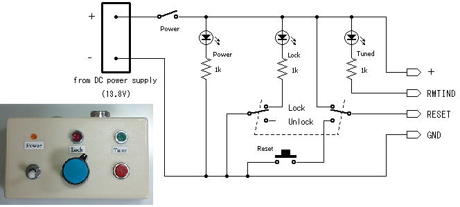 Fig.8 |
|