Bandscope of TS-590S Ver. 1.0 25 Aug. 2016 All rights reserved JA3OOK Toshikazu Nakamura This is explanation of Bandscope by TS-590S. 1. Overall block diagram
 2. Takeoff of IF
I read carefully TS-590S SERVICE MANUAL(Reference materials 1), especially 131 pages
schematic diagram. and paid my attention to CN301 connector of TX-RX UNIT.
I seem to be able to take the broadband reception signal which is in just before the
first step IF filter (roofing filter) in the down conversion.
It is down conversion, So only 160/80/40/20/15m band, and It is less than reception
DSP filter bandwidth 2,700Hz, but it is enough for me.
3. Design and Make "IF Adapter"
The specifications found to this IF adapter are as follows.
* The amplifier that input impedance is super high.
I see SIGNAL LEVEL DIAGRAM(SERVICE MANUAL 162 pages).
The level of CN301 is -107dBm. is unexpectedly small.
* Output low impedance to input impedance of the SDR.
First RF amplification IC of Soft66Lite is ��PC1688.(Reference materials 2)
The input impedance is 50 ohm.
This ia the circuit diagram and photograph.
2. Takeoff of IF
I read carefully TS-590S SERVICE MANUAL(Reference materials 1), especially 131 pages
schematic diagram. and paid my attention to CN301 connector of TX-RX UNIT.
I seem to be able to take the broadband reception signal which is in just before the
first step IF filter (roofing filter) in the down conversion.
It is down conversion, So only 160/80/40/20/15m band, and It is less than reception
DSP filter bandwidth 2,700Hz, but it is enough for me.
3. Design and Make "IF Adapter"
The specifications found to this IF adapter are as follows.
* The amplifier that input impedance is super high.
I see SIGNAL LEVEL DIAGRAM(SERVICE MANUAL 162 pages).
The level of CN301 is -107dBm. is unexpectedly small.
* Output low impedance to input impedance of the SDR.
First RF amplification IC of Soft66Lite is ��PC1688.(Reference materials 2)
The input impedance is 50 ohm.
This ia the circuit diagram and photograph.


 At impedance and amplification degree are high as for 2 pin sockets,
I shield a wall with a metal plate because sensitive to the electric field.
The rheostat is for gain adjustment. I adjust it at a good balance with the gain
adjustment of Soft66Lite.
The size of the base is 37mm * 22mm.
The photograph which I open bottom cover of TS-590S and took is the left side.
A rectangle of the white is CN301.
I place the pin of this CN301 into the pin socket of the base, and connection of the
wiring with the SDR is a photograph on the right side.
At impedance and amplification degree are high as for 2 pin sockets,
I shield a wall with a metal plate because sensitive to the electric field.
The rheostat is for gain adjustment. I adjust it at a good balance with the gain
adjustment of Soft66Lite.
The size of the base is 37mm * 22mm.
The photograph which I open bottom cover of TS-590S and took is the left side.
A rectangle of the white is CN301.
I place the pin of this CN301 into the pin socket of the base, and connection of the
wiring with the SDR is a photograph on the right side.
 �@
�@ Do a bottom cover after I cover a base with a small plastic bag because do not let
contact a bottom cover.
4. SDR hardware
This is the hardware of SDR.
Do a bottom cover after I cover a base with a small plastic bag because do not let
contact a bottom cover.
4. SDR hardware
This is the hardware of SDR.
 Right side of above are SDR BOARD.
It's Soft66Lite by JA7TDO.(Reference materials 2)
Left side are DDS BOARD.
It's AD9834 SMALL MODULE KIT by strawberry-linux.(Reference materials 3)
Right side of under are MCU BOARD.
It's home made frequency controler by me.
I put PIC18F25K22 on the boad, and programming, too.
I am documenting detail of the SDR hardware,
it is a different website. (Language is Japanese)
when frequency to give to SDR is 11.374MHz (that is central frequency of IF),
there are many spurious bars which a bandscope shows.
I choose 11.376MHz as a result of experiment.
5. SDR software
I am using SDRsharp(SDR#).(Reference materials 4)
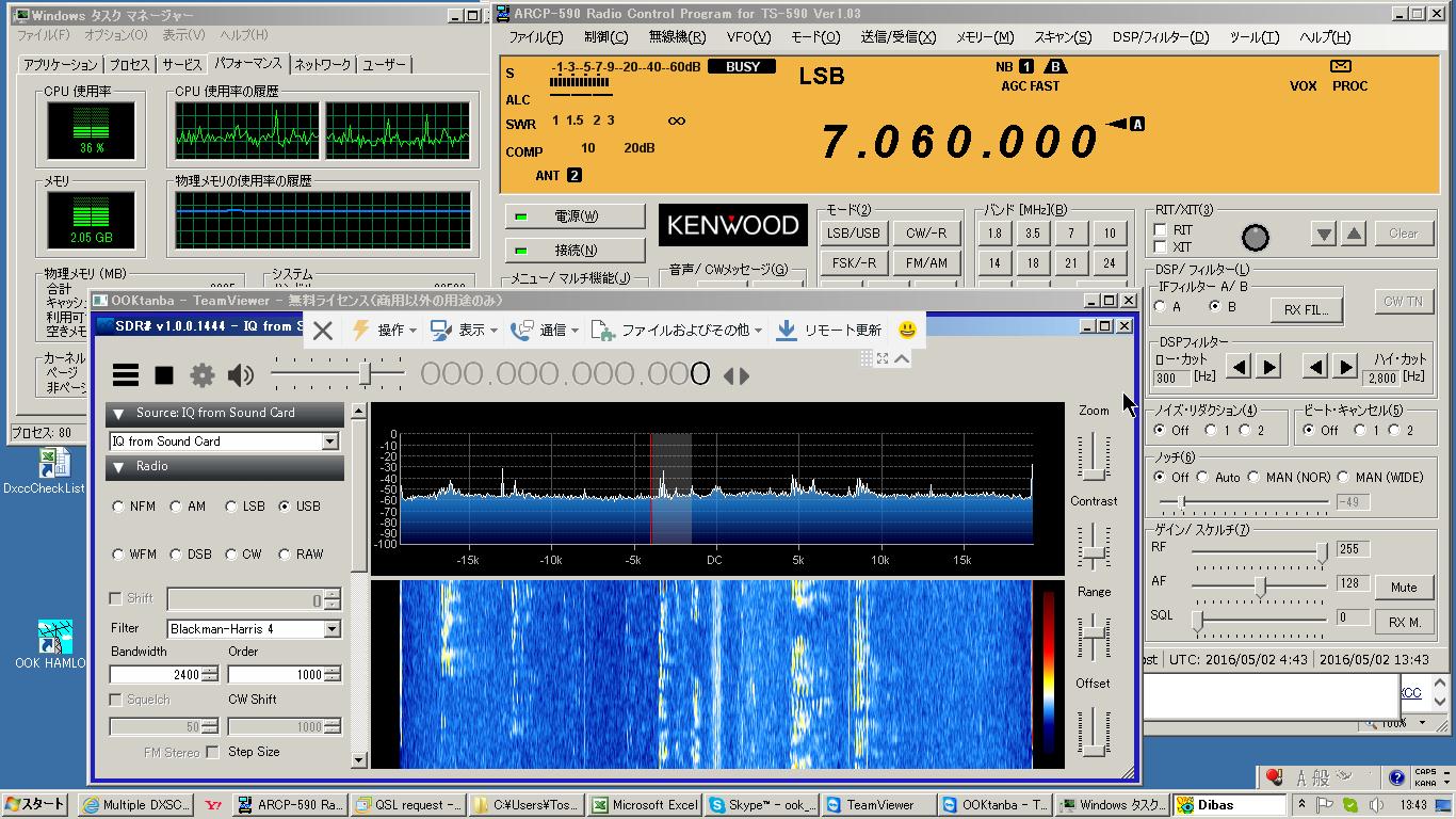
6. The use by the remote control
If necessary from remote station, can view the bandscope.
Because the bandscope is displayed on the PC screen of the transmitting station,
using "Remote Desktop" is OK.
I am using "Team Viewer" now.
This is a screen example of the PC on the remote control side.
Right side of above are SDR BOARD.
It's Soft66Lite by JA7TDO.(Reference materials 2)
Left side are DDS BOARD.
It's AD9834 SMALL MODULE KIT by strawberry-linux.(Reference materials 3)
Right side of under are MCU BOARD.
It's home made frequency controler by me.
I put PIC18F25K22 on the boad, and programming, too.
I am documenting detail of the SDR hardware,
it is a different website. (Language is Japanese)
when frequency to give to SDR is 11.374MHz (that is central frequency of IF),
there are many spurious bars which a bandscope shows.
I choose 11.376MHz as a result of experiment.
5. SDR software
I am using SDRsharp(SDR#).(Reference materials 4)
6. The use by the remote control
If necessary from remote station, can view the bandscope.
Because the bandscope is displayed on the PC screen of the transmitting station,
using "Remote Desktop" is OK.
I am using "Team Viewer" now.
This is a screen example of the PC on the remote control side.
 Reference materials
1 Kenwood Corporation TS-590S SERVICE MANUAL
2 JA7TDO Soft66Lite
3 strawberry-linux AD9834 DDS Small module kit
4 Analog devices AD9834 datasheet
5 AIRSPAY SDRsharp
6 TOSHIBA 2SK192A datasheet
7 TOSHIBA 2SC1815 datasheet
Reference materials
1 Kenwood Corporation TS-590S SERVICE MANUAL
2 JA7TDO Soft66Lite
3 strawberry-linux AD9834 DDS Small module kit
4 Analog devices AD9834 datasheet
5 AIRSPAY SDRsharp
6 TOSHIBA 2SK192A datasheet
7 TOSHIBA 2SC1815 datasheet